
As the digital society develops, expectations of the telecommunications infrastructure are also increasing. To ensure fast and reliable data transmission, operators now use innovative xWDM technology.
What does xWDM really stand for, how does the technique work, and how are networks built using it? Find out in today’s article.
What is WDM?
WDM is a so-called wavelength-division multiplexing technology used to increase the transmission capacity of an existing optical fiber network. It is based on a multiplexing method in which multiple optical signals from different sources, with different power and different wavelengths called colours, are transformed and transmitted simultaneously within a single optic fiber.
In the field of telecommunications, frequency division multiplexing is a technique that divides the available bandwidth in a transmission medium into several non-overlapping bands, each of which is used to transmit a different signal. In this way, it is possible to transmit multiple independent signals through a single unit of the transmission medium shared by these signals.
This translates into the simultaneous parallel transmission of multiple signals, thus achieving higher bandwidths in transmission. The most common example of such multiplexing is radio transmission or television transmission, for which multiple signals of different frequencies are propagated simultaneously in the transmission medium, which in this case is air.
Why „X” WDM?
The letter ‘X’ at the beginning of the technology’s name is nothing more than the designation of the two main techniques that make up the technology – CWDM and DWDM.
CWDM (Coarse Wavelength Division Multiplexing) allows the transmission of up to 18 channels with wavelengths from 1271nm to 1611nm. On the other hand, DWDM (Dense Wavelength Division Multiplexing) currently allows 96 channels to be transmitted. Solutions for the transmission of 8, 16, 40 and 80 channels are also common. In addition, it is worth noting that the DWDM technique is characterised by a much greater transmission range than CWDM. It reaches up to several thousand kilometres.
Both techniques increase the efficiency of fiber optics use. They are characterised by their compatibility with all network equipment and scalability, which allows additional channels to be added freely. A key feature is transparency, meaning that the system is transparent to any type of signal.
How is an xWDM network constructed?
We distinguish between two methods of building networks using xWDM technology – passive and active.
The first, passive, involves the installation of CWDM or DWDM standard optical modules and passive optical filters in the network equipment. On the other hand, active is based on solutions directly related to the transmission of signals in the wave multiplexing system, such as transponders and muxponders, while offering additional functions, such as a management system or monitoring.
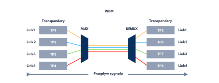
The figure below shows an example of an active DWDM network architecture.
Looking from the left, we can distinguish a number of signals coming from the end devices labelled Link1 – Link4. These go to the hardware part, i.e. the transponders (TP1 – TP4), which receive the client form of the signals and convert them to a linear form in DWDM standard. Then there are the DWDM MUXes, which aggregate signals of different frequencies (wavelengths) coming from fibers coupled to the linear part of the transponders. Such aggregated signals are sent by the MUXes from their line output. On the other side we have an analogous situation (mirror image). The combined signal from multiple aggregated frequencies reaches the line port of the DEMUX, from where it is distributed into individual signals of a given wavelength. In this form, they are transmitted to the ports assigned to a specific channel (frequency). These ports are connected to the linear part of the receiving transponder (TP5 – TP8), which converts them to client form. In this form, the signals are transmitted to the terminal equipment at the receiving node (Link1 – Link4).
The situation described shows the signal flow from left to right. In standard bi-directional transmission (single or dual fiber), signal transmission in the other direction is analogous.
Today, xWDM technology is an indispensable solution for telecommunications infrastructures, guaranteeing fast and reliable data transmission.

Would you like to apply xWDM to your network?
Contact us!
